
Radio navigation
|
This page explains the principles of radio navigation to you.
As is probably generally known, the basis of radio navigation consists of emitting and receiving electromagnetic waves.
I would like to do without further details and further "physics lessons" and turn to the interesting and important area for us "flight simulators". Basically, a distinction is made between internal and external sounding: In self-direction finding, the pilot uses certain instruments on board his aircraft to determine direction and/or location. There are two known devices of this kind:
In the case of external sounding, direction and/or location is determined by means of appropriate equipment installed on the ground. The two best known methods are:
The omnidirectional beacon, called NDB, emits an omnidirectional electromagnetic field in all directions.
A distinction is made between RADIO FIRES with a range of up to 100 NM and LOCATORS with a range of up to 25 NM. A range beacon has an identifier of three letters, an approach beacon has an identifier of two letters. On ICAO charts this identifier is printed together with the frequency in KHz: Name
Frequency in KHz
Abbreviation
NECKAR
292
NKR
LIMA
311
LMA
BOTTROP
406.5
BOT
DUSSELDORF
417
LI (Approach beacon Rwy 23L)
DUSSELDORF
284.5
DY (Approach beacon Rwy 05L)
The waves emitted by an NDB station are received by an automatic radio direction finder. This is called ADF (automatic direction finder). The ADF shows the direction from the aircraft to the set NDB station, where the aircraft longitudinal axis is the reference direction. The angle between the aircraft's longitudinal axis and the NDB station is called relative bearing (RB) or radio direction finding. It is indicated clockwise. 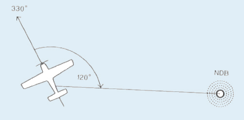 relative bearing RB = 120° Four prominent positions and their ADF display: Note: The needle of the ADF always points to the NDB station 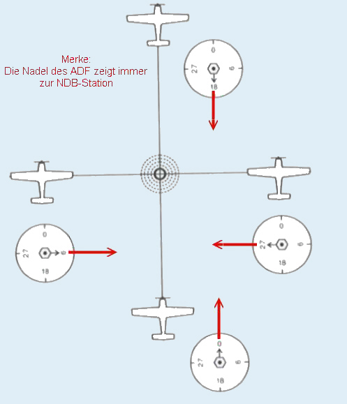
A VOR station operates in the frequency range 111.975 to 117.975 MHz and emits 360 radials, hence the term RADIAL.
The radials are designated according to their misleading direction away from the ground station (QDR). You can imagine them like the spokes of a wheel. Radial 090 points directly east away from the ground station, radial 270 points west, etc. The radial of a VOR station: 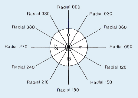 The VOR receiver on board has a reception range from 108 to 117.975 MHz; it can also receive the landing course transmitters of the instrument landing system (ILS), which operate in the range from 108 to 111.975 MHz. The on-board VOR receiver provides the pilot with two important pieces of information:
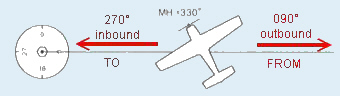 An aircraft is flying on a magnetic heading (MH) of 330° and is located exactly east of a VOR station. The pilot sets the frequency of the VOR station and turns the omni bearing selector (OBS) until the CDI needle is in the middle. When the course selector is rotated through the full 360 degrees, the CDI needle will be centered twice:
For example, an air traffic controller could give the pilot instructions: Fly on radial 090 outbound. It is very important that the pilot selects the correct one of the two possible settings of the course selector. If he wants to fly away from the station, he sets the course 090° with the display FROM. In this case the designation of the radial (in the example 090) corresponds to the selected course. If he wants to fly towards the station, he has to set the opposite course (i.e. 270°) to get the display TO. In this case, the selected course and the radial designation differ by 180°. outbound - Display FROM selected course = radial designation inbound - Display TO selected course = radial designation +/- 180° VOR receiver as command deviceOnly when the course selector is set correctly does the VOR receiver operate as a command device.Here is another example: 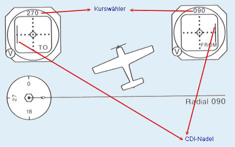 In the meantime the plane has continued its flight and is located north of the radial 090. The pilot wants to fly away from the station on radial 090. It sets the course selector to 090° and displays FROM. The CDI needle is on the right because the desired radial is on the right, when it looks at its current position in the direction of 090°. So he must fly to where the CDI needle points; it gives him commands. If he wants to fly on radial 090 towards the station, he sets the counter course on the course selector, i.e. 270° with the display TO. Now the needle is on the left because the desired radial is on the left when looking in the 270° direction. Again the needle gives the command where to fly to.
One procedure that the pilot often has to perform is the intercept of a radial.
The instruction of our air traffic controller could for example be:
Condor 0815, intercept radial 250 and proceed inbound XXX VOR. A radial is cut at 45° as standard. Also 30° or 60° are possible. If the current position is known, you immediately know where the radial to be cut is located. Otherwise, fly a course parallel to the radial to be cut and observe the deflection of the CDI needle. Here an example: An aircraft is located southwest of a VOR station, but the pilot does not know his current location relative to the VOR station. It receives the following instruction: Intercept radial 225 and proceed inbound VOR station. Since he is to fly inbound on the Radial 225, the course selector must be set to the opposite course 045°. The display shows TO. The pilot flies this course for a short time and observes the deflection of the CDI needle. In the example, the needle points to the right, so the pilot knows that he is north of radial 225. Now it calculates the cut-off course by adding 045° to its current course. With 090° he cuts the radial 225. He observes the needle as it moves slowly from right to center. Just before it reaches the center position, it changes course to 045°. The clean curve on a radial to be cut is a matter of practice, which can be trained well in the simulator. There is no patent remedy here, because the single-curve process depends on several factors: the distance to the ground station, the airspeed and the wind conditions. 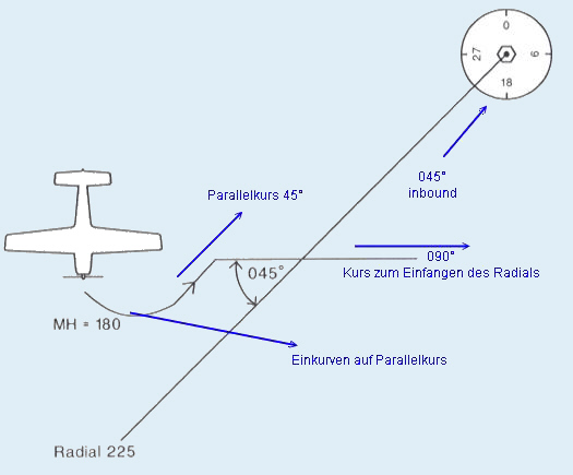 Here we continue with an example for the typerating of the Condor-VA for the First Officer and the Captain. We are on approach to Düsseldorf airport. We are approaching from the south and have chosen WIPPER3G as our arrival route (STAR), as we are landing towards the west. We are currently on the Radial 348 outbound WYP. Or the other way round: on the Radial 168 inbound BAM-VOR. The decisive factor here is which frequency is locked in the NAV1 receiver. This radial leads us directly to the VOR-BAM. 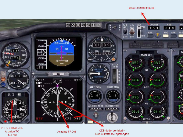 Here the BAM-VOR has already been flown over and we follow the Radial 310 outbound. The frequency 113.6 for BAM was locked into NAV1. We also get a distance indication DME. NAV2 was set to the place-VOR DUS 115.15. This shows us the correct distance to the airport. Furthermore the ADF receiver should be adjusted to the locator of the Rwy 23L. (LI 417). 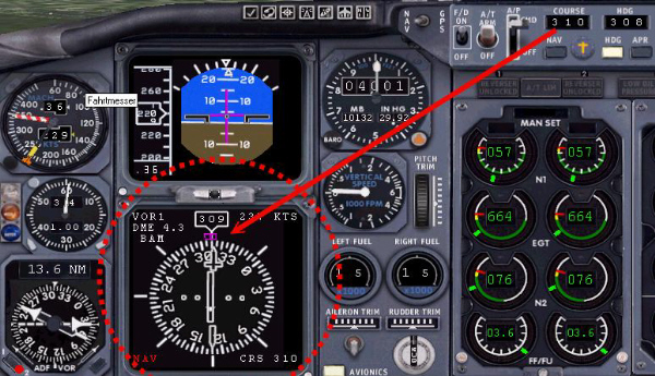 In the further course of the flight, we now switch to the frequency of the ILS (instrument landing system) in NAV1. For the 23L this is 109.90. In autopilot mode, the pilot switches to APR mode (standard Microsoft machine), or in more realistic aircraft (PSS, Dreamfleet, PIC) the LOC mode is activated. This one puts us right on course for landing. As soon as this is caught, the APP mode is added and we "slide" on the glide path to the runway. Everything else should then no longer be a problem. ...right? We hope this little introduction to NDB and VOR navigation could close some knowledge gaps and help you to be always on the right radial in the future We do not want to go into the further possibilities that VOR and NDB still offer us (location determination - cross-bearing with the aid of two VOR stations, distance determination in the absence of DME, NDB homing procedure, approach with NDB at the airfield, NDB as landing aid, etc.) here, as it would go beyond the scope of this article. This may be supplemented at a later date. For requests, suggestions or errors: |